Mechanical Design
Engineering Principles in Action
Materials, Fabrication, and the Road to Manufacturing
From concept to manufacturing, our staff uses engineering principles to guide decision-making. This process ensures that each stage of the project is both efficient and effective. At the concept stage, we focus on feasibility, form, and design. We also assess the manufacturability of the concept and identify potential risks. In the next stage, we move from estimation to detailed calculations and computer modeling. This includes mechanical engineering considerations such as material selection and stress analysis as well as building functional prototypes. Finally, we translate the results of our prototype iterations into production through Design for Manufacture for the appropriate high-volume fabrication techniques. By using engineering principles at every stage, we are able to create products that are both high-quality and cost-effective.
More than product designers, we’re specialized engineers. We obsess over the details and won’t quit until it works. Go ahead, bring us what you got.

Form & Function
Part Design
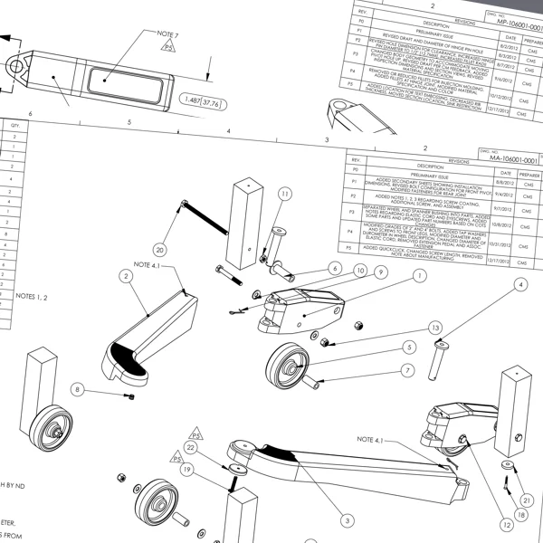
Mechanical engineering and design is a critical process in the development of any mechanical system. The first step is to design a mechanism that will achieve the desired function. This likely involves a mixture of off-the-shelf items such as gears, bearings, and motors with custom brackets, linkages, or enclosures. The next step is material selection, which must take into account the desired properties of the final product, such as strength, stiffness, wear resistance, and manufacturability. Finally, the dimensions and tolerances of the parts must be carefully examined to ensure that they will fit together correctly and perform as intended.
Design for Manufacturing
Design for Manufacturing, or DFM, is the process of designing parts and products to be manufactured in the most cost-effective way possible. This includes taking into account the materials to be used, the machines and processes required, and the tolerances that can be achieved. Injection molding, machining, sheet metal forming, laser cutting, waterjet cutting, vacuum forming, and 3D printing are all standard manufacturing processes that we use to fabricate parts and products. Each process has its own strengths and weaknesses, so it’s important to choose the right one for the job at hand. We’re typically using low-volume production techniques for in-house prototyping and transitioning to high-volume processes for production manufacturing. At Root3 Labs, we have cut, sawn, lasered, printed, molded, bent, smashed, and burned just about anything you can imagine.
Engineering Tools
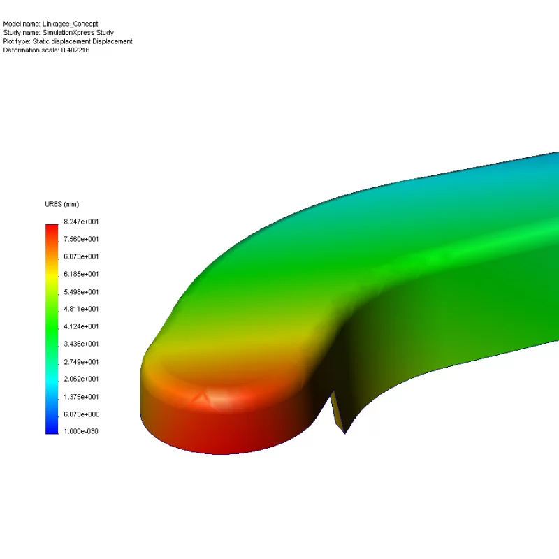
Everyone loves the fabled sketch on the back of a cocktail napkin, right? In keeping with our typical mindset, we try to make practical use of the least complicated tools available, so we’ll often start with sketches and hand calculations. However, to help the idea become reality, we’ll also use a variety of software tools to support our engineering and prototyping process. Solidworks CAD is used to create 3D designs and perform simulations using finite element analysis (FEA). Fusion360 CAM is used to turn CAD designs into manufacturing toolpaths for the CNC Mill or Router, while CorelDraw is used to turn 2D shapes into laser-cut plastic or plasma-cut metal parts. Simplified mathematical modeling and data analyses can be performed in Matlab, SMath, or Excel, while complex real-time analyses might require us to build custom software tools in C++, Python, or embedded firmware. In addition, we use a variety of other software tools to help with project management, revision control, and design documentation.
Gallery