High Performing Ground Support Equipment
Delivered in 10 Weeks
Ground Support Equipment Delivered
When 7m diameter, 4,000 kg rocket parts are on the way, but you still need a system to manage them in-house, you need GSE fast – 10-weeks fast. Key performance achieved. Problem solved.
The adapters and the lift carts have been indispensable for an ever shrinking factory floor.
For aerospace manufacturing, precision and reliability aren’t just “important” – they’re essential. Our client was working on developing their newest project and needed specialized equipment to support their carbon fiber rocket component fabrication and assembly processes.
They came to us with tight timelines, demanding size and load constraints, and evolving requirements.
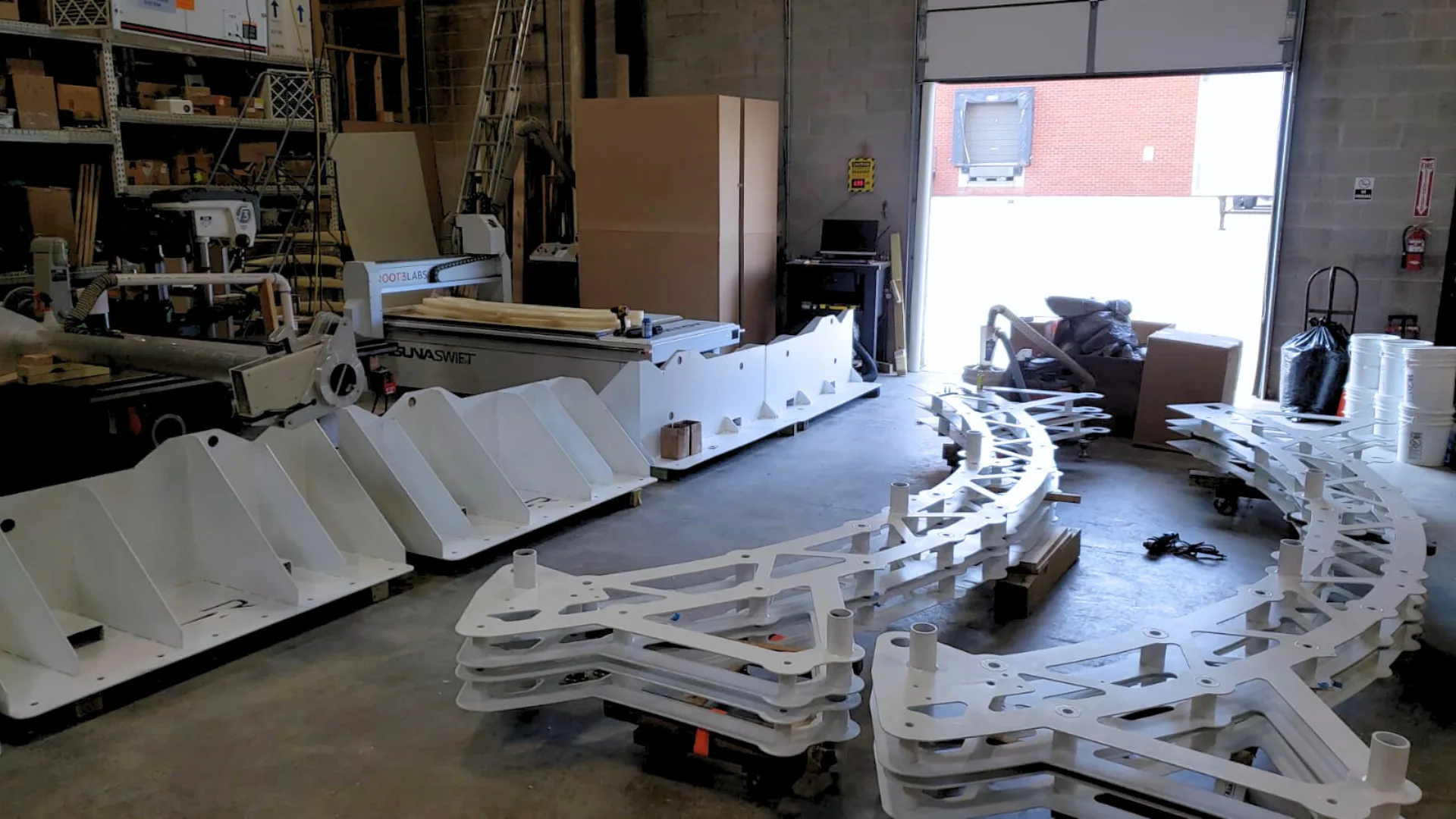
Our client’s innovative approach to Aerospace Manufacturing involves a 3D printing robot – the world’s largest of its kind! – that precisely applies carbon fiber to specialized molds. This autonomous machine is expected to save hundreds of thousands of manufacturing hours in the rocket’s production process.
The 3D printing system produces all of the large composite structures for the rocket’s launch vehicle, including the massive panels for the body, fairing, and first & second stages.
Due to the massive size of these components and our client’s goal for rapid production turn-around, the manufacturing process required custom equipment to position, rotate, and transport these multi-ton, uncured fiber structures throughout their facility.
Our team at Root3 Labs set out to design and fabricate specialized Ground Support Equipment (GSE) that would support this demanding manufacturing process. Our role was to have the new GSE delivered ahead of their aggressive production schedule while ensuring the critical precision and safety required for aerospace applications, supporting the creation of one of the most advanced launch vehicles in development today!
Ground Support Equipment (GSE):
In Aerospace Manufacturing, Ground Support Equipment (GSE) refers to the non-flight equipment used in the assembly, integration, and testing of spacecraft and launch vehicles.
MGSE (Mechanical Ground Support Equipment) specifically handles the physical manipulation of components – a critical but lesser known aspect of aerospace manufacturing.

The Challenge
The most significant hurdle for this project was time. When they first came to us, our client had critical parts arriving soon and would need these specialized systems in place to hold and manipulate those parts before they arrived.
With very tight timelines, they needed to procure specialized equipment with two distinct but equally critical manufacturing challenges.
Phase 1: Adapter and Transport Lift System
The carbon fiber printing process needed equipment to safely support and transport the heavy molds used with the robot. Initially the equipment was imagined to be a separate adapter base for the tooling, and a heat-tolerant cart to carry everything into the oven for curing.
However, we realized that we could reduce the complexity of the system and cut development time by designing an adapter that wouldn’t require the cart to stay in the oven. This change opened up many possibilities for lifting actuators, motors, and other electronics that wouldn’t have been able to tolerate the oven’s elevated temperatures.
Phase 2: The Rotational Fixture
Our client needed rotation, alignment, and joining capabilities for high aspect ratio carbon panels. They were looking for a system that could help them precisely position, rotate, and join the large carbon fiber panels that make up the rocket body.
As our CEO, Chad, noted from the start of this project: “We’re optimizing for time here. The way to do that is to be most effective with your focus and your effort. Overdesign it for safety and strength and minimize functionality to only what’s necessary. Don’t get stuck on details or decisions that don’t affect the outcome.”
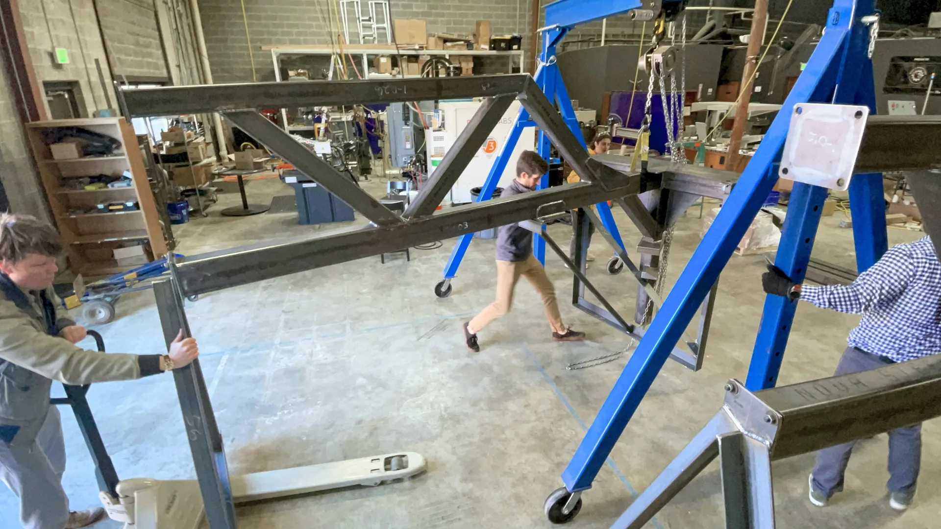
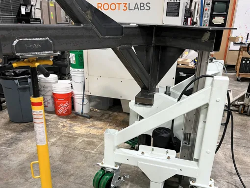
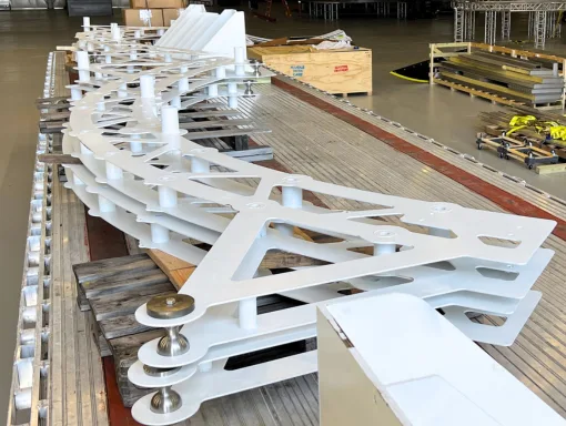
Part of the process was planning for the transportation of this three-legged Adapter, so we integrated bolted joints with the welded structures as well as stability fixtures.
Our Process - A Two-Phased Approach
The first step was understanding just how the manufacturing, assembly, and joining processes worked. We needed to visualize how components would move through their facility: from the initial mold positioning to the robot application, to the curing oven, and finally to the staging platform where the rocket would be assembled.
Once we had a clear idea of the workflow, we began the design process. For both phases of this project, we followed our proven engineering process, adapting to the specific requirements of each unique challenge.
Phase 1: Adapter and Transport Lift System
Concept Generation & Initial Design (Week 1)
We started with a rapid concept development process, working very closely with our Customer’s internal team. Within just 5 days of our initial kickoff, we presented multiple concepts and got the green light to proceed with the winning design for the adapter and transport lift system.
Engineering Analysis & Verification (Week 2-3)
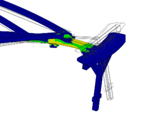
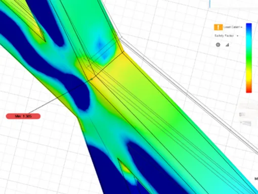
The designs underwent thorough Finite Element Analysis (FEA) to validate load-bearing capacity, analyzing static loads, and stress points at critical connections. The computer aided FEA process combined with meticulous hand calculations are critical to ensure our designs would safely support the necessary loads with an appropriate Safety Factor.
Critical Design Review (Week 3)
Just 3 weeks after project kick-off, we completed our Critical Design Review. Our design reviews are created to catch errors before investing in costly engineering efforts.
Fabrication & Assembly (Week 4-8)
We coordinated with specialty vendors, like welders, machinists, and sheet metal fabricators, while building select components in-house. Throughout fabrication, we maintained rigorous quality control with on-site testing and fit checks.
Integration & Testing (Week 8)
Before delivery, we conducted comprehensive testing of the assemblies, verifying load capacity, synchronized lift operation, and safety features including limit switches.
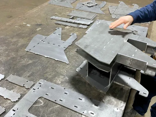
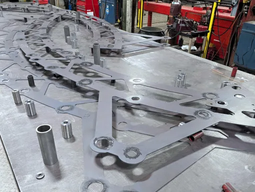
Tab & Slot features for this sheet metal weldment were a real time-saver. They allowed both fast and precise assembly for welding rather than having to build secondary fixtures.
Phase 2: The Rotational Fixture
Concept Generation & Initial Design (Week 1)
Building upon our successful Phase 1 work, we applied the same rapid concept development process to end up with the winning rotational fixture system design. Our team nicknamed this assembly, ‘The Bean’!
Engineering Analysis & Verification (Week 2-3)
For this system, we focused our FEA and hand calculations on issues like dynamic loads during rotation, floor mounting stability, and precision alignment capabilities.
Critical Design Review & Documentation (Week 4)
We created comprehensive documentation for the Bean’s rotational mechanisms, hoist systems, and electrical controls. Our Critical Design Reviews always included our client ahead of final assembly to ensure that everyone is aligned and that the designs meet all necessary requirements.
Fabrication & Assembly (Week 5-8)
Working with the same trusted vendor network, we started fabricating the larger structural components while developing and testing the control systems in-house.
Integration & Delivery (Week 9-10)
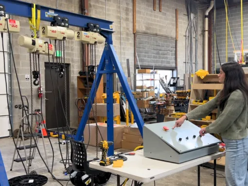
We tested safety features such as the emergency braking system of the ‘Bean’ hoist controls and carefully packaged everything for delivery.
The Solution
Our project delivered two comprehensive systems to support our client’s manufacturing processes:
Adapter & Transport Lift System
- A custom adapter designed to interface with the existing rotator and mold.
- Three transport lift carts capable of safely moving and positioning the adapter and tooling with perfect synchronization.
- Integrated control systems to safely operate the transport lift carts.
The adapter and transport lift system allows our client to position their molds precisely for the automated carbon fiber application process, then transport them to the curing oven once printing is complete.
Interstage Rotational Fixture
- Custom rotational fixture allowing positioning of large-format carbon fiber panels from horizontal to vertical.
- Floor-mounted design to provide stability during critical alignment operations.
- Ring positioning fixtures to ensure precise component alignment.
- Integrated hoist system with electrical controls and emergency braking.
With this assembly, our client will be able to join the large carbon fiber panels with precision alignment, rotating them between horizontal and vertical positions as needed during the assembly process.
In Aerospace Manufacturing, precision is not an option; it’s a requirement. Our equipment was designed to maintain precise positioning under load, with smooth operation and integrated safety features.
The Results:
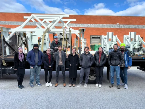
Root3 Labs delivered both systems on schedule, meeting our client’s rigorous design requirements and demanding timeline. We’re honored to supply equipment that now forms a critical part of their manufacturing process, enabling them to:
- Support their complete carbon fiber manufacturing workflow
- Safely transport and position their heavy carbon fiber molds
- Maintain precise alignment during carbon fiber application and panel assebly
- Reduce assembly time through purpose-built positioning equipment
Need Ground Support Equipment?
Our work demonstrates our ability to rapidly design and deliver critical Aerospace Manufacturing Equipment under tight timelines.
By singularly focusing on what matters most to our customers and maintaining clear communication throughout the entire process, we deliver solutions that enable cutting-edge Aerospace Manufacturing techniques.
