Making It!
The Badge Challenge: Part Two
If you missed Part 1 of the Badge Challenge, check it out here!
-Or continue with Part 3 of the Badge Challenge here.
Negotiating design details is always tricky, but especially when the electrical and mechanical teams have different priorities. But with this project, our small crew defied the odds with a collaborative sprint all the way to the finish line.
We ditched the usual segmented approach of different teams working in isolated silos in favor of ongoing collaboration between all segments. Our electrical and mechanical leads, Christina and Chris, worked side-by-side, hammering out design details in real-time. This rapid, collaborative process, fueled by our tight-knit team dynamic, powered us through the 4-week turnaround.
Once the printed circuit boards (PCBs) were ordered, we jumped right into testing and fabrication that could be completed during the five days it would take the bare boards to arrive.


Electrical and Software
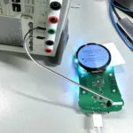
The electrical/software team began with software development. The goal was to have as much software as possible built and ready for testing as soon as we had the boards in hand. This included the basic structure of our code to run with the display, the drivers for the 18-channel LED controller, and the drivers for the pulse ox sensor.
The code was tested against the display’s development board and the design documentation. Ultimately, the custom printed circuit boards would replace the development board that came with the display, but it proved useful for initial testing.
3D Printing and Mechanical Design
In parallel, the mechanical team 3D printed the enclosure on our in-house SLA printer. The 3D-printed enclosure was meticulously checked for the fit of all components, including mating parts, the display and battery, and the soon-to-arrive Printed Circuit Boards.
When the boards initially arrived, the mechanical team confirmed the fit of the assembly with an unpopulated PCB and 3D printed thumb contacts while the machined versions were being fabricated.
The mechanical team also started the fabrication of the two thumb contacts. These would be to create an ergonomic conductive path between the user’s thumbs and the custom PCB for the EKG function. The contact points would also be able to supply access to a pulse ox sensor mounted directly to the PCB.
Our key to victory? Our In-house workshop.
A huge benefit to having a fully equipped workshop is the ability to rapidly produce parts in-house. Similar parts could take weeks in a standard machine shop queue. With our in-house Fadal Vertical Machining Center (VMC), the mechanical team was able to produce 6 thumb contacts (2 per unit) in a matter of days. The contacts were machined out of stainless steel as opposed to aluminum to maximize conductivity.
Originally, we had planned to use aluminum for the thumb contacts because we knew it would be quick to machine. However, aluminum would oxidize over time in the presence of finger oils without any anodization. And if we did anodize the material, the anodization and the oxidation would also limit the conductivity from the finger to the board. This was a real time materials decision, and because of our collaborative full-team approach, we were able to instantly change gears and go in a completely different direction.
So, we turned to stainless steel! Stainless Steel requires more power to machine, but the Fadal stepped up to the plate with its 15 horsepower, 10,000 rpm spindle. The 21-piece automatic tool changer makes jobs like this heavy on the setup and easy on the machining because the roughing cuts, finishing cuts, and hole tapping can all be done without any operator input.

Hand Wiring a Fix in a Pinch
During the machining process, the custom printed circuit boards arrived. With parts in hand, the electrical team worked to manually populate all 3 boards. Even though we had two people working, this process took hours! It involved using tweezers to position 150 components per board with solder paste and then placing the boards in a reflow oven to flow the solder.


During this process, we identified a single component out of the 150 that had an error on the board footprint. In a typical project, the board design would be updated and reordered. This 4-week timeline had no room for a 5-day delay, so Christopher (our electrical lead) crafted a plan. They would glue the offending chip upside-down and then recruit someone with incredible patience to come in and hand solder magnet wire from the chip to the pads on the board.
Christina offered to try! With a good audio book, a pair of tweezers, some solder paste, magnet wire, and a microscope, she got to work routing the fix. Incredibly, this worked!
At this point, the code could finally be validated against the electrical design, so the electrical team was off running again to solidify the software.

The Work of Finishing
With the mechanical design locked in, our “finishers” got to work.
With the Fadal to machine the stainless steel thumb contacts, the only hurdle to getting them done was making sure we had all the correct settings locked in. It took maybe six or seven cutting attempts to get the final finish we liked. This was an iterative process, achieved by taking the most current result and continuing to cut down with the Fadal’s different tools. Once the thumb contacts were up to our finisher’s exacting standards, he did a final sweep on the parts with a small bit and close stepover to finish them off.
We unlocked a hidden talent of one of our engineers who professionally finished mock-ups of hand tools previously in his career. He worked with Conrad to sand, prime, sand, prime, sand again, and then paint our prototypes – a true labor of love!
“Finishing work is very therapeutic. Techniques like sanding require a lot of patience and time. I love the feeling of zoning in on a task.” He said.

To fully finish the thumb contacts they would need polishing up. At the last second, Chad decided he wanted the steel to have a matte finish. So, we pivoted to achieve that matte finish through sandblasting – which sounds a lot more exciting, than it really is.
The final touch was a fiber laser engraved nameplate with colored enamel filling in the letters. To achieve the perfect look, we experimented with different enamel colors and held a team vote to pick the winner. (Sadly, Root3 Orange was not the winner).
After engraving the nameplate, our finisher meticulously hand-painted the recessed areas with various colors, testing each one for the desired effect. Finally, for a smooth metal finish, the nameplate was carefully sanded down on flat granite using sandpaper. This process ensured the paint stayed within the recesses while creating a smooth, polished surface on the top.

Putting It All Together
With the electrical, software, and mechanical teams working in tandem, the badge looked like it was coming together just in time for MEDICA! This truly was a full team effort. The tight 4-week timeline pushed us to focus on the minimum viable product (MVP) features, solve problems in unique ways, and constantly communicate across disciplines. Thank goodness our team loves a good challenge!
Wondering How to Get YOUR Product
Development Process Right?