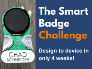
With the Smart Badges fresh off development, our team headed to #MEDICA2023 in Germany! Talk about an exciting debut for our newest gadget. This Nifty Name Tag was the perfect thing to quickly demonstrate some of our key capabilities in the bustling atmosphere of over 5,300 exhibitors and 83,000 visitors.
Conrad, our Director of Engineering, manned our booth to greet visitors and showcase some of our other innovative designs. Meanwhile, Chad, our CEO & Founder, equipped the Smart Badge and set out on foot to explore the latest advancements in medical products and services. We even did the math – Chad walked an impressive 28 miles over the five-day conference, leaving Conrad just a little jealous! Even in this early stage, the Badge attracted attention and sparked lots of conversations with other attendees!
In just four weeks we turned our innovative idea into a reality, and that’s really what we do here at Root3 Labs! This project enforced for us some important lessons in product development and device design. It was clear that our success came down to three key things:
- Prioritizing Ruthlessly: Focusing on the Minimum Viable Product (MVP) allowed us to achieve core functionality within a tight time frame.
- Close Cross-Disciplinary Collaboration: Seamless, close (and we do mean close!) communication between each discipline involved ensured everyone was aligned and always working towards the same goals.
- Mastering the Timeline: With such a tight development window, every day really does count!
These are tools that we use in every project, and you probably do too! But, having to pare everything down to their bare essentials allowed us to pay attention to what are the strategies that help us achieve a successful outcome.
Optimizing Workflow in Time-Constrained Projects

Given the tight timeline, identifying the critical path was the first and most important step. We knew there would need to be electrical, mechanical, and software components involved in the overall design. In order to meet the deadline, each team would have to work in parallel with close collaboration.
While in-house fabrication would greatly reduce lead times for mechanical components, the same would not be true for the Printed Circuit Boards (PCBs). We can populate boards in-house, but we currently outsource bare board PCB fabrication. Although the turnaround time was rapid – as little as five days – it would still be our biggest bottleneck in terms of time. This meant that PCB design and fabrication would emerge as the Critical Path for the project.
Tip: This is is a tactic we use in ALL of our projects to stay on schedule! The critical path is a moving target and changes as the project progresses. Don’t be afraid to shift your path when needed!
We determined that we wanted to order the boards by the end of the first week to leave enough time to receive, populate, and test the boards before final assembly. Recognizing the need for early PCB ordering, we aimed to solidify features, identify components, and finalize the board design within the first week. This necessitated a collaborative effort: the electrical team selected components while the mechanical team defined component footprints. These efforts converged to finalize the design. The remaining tasks also had tight timelines, but without ordering and receiving the boards on time, we would not have met the final deadline.
Besides identifying the critical path, we allocated the most time for the design of the device – both electrical and mechanical. We didn’t have time for multiple physical iterations, so it was essential to “measure twice and cut once” by spending the required time in the design phase. Even with our attention to detail, we still had to come up with creative ways to solve design issues – take a look at “Hand Wiring a Fix” in Part 2 of our blog series. Thank goodness we love hard problems!
Collaboration in Action
We always work together closely (it’s not that big of a workshop!), but it was a tactic that definitely paid off with this project. The early electrical and mechanical design was boosted by the fact that Christina, the mechanical lead, and Chris, the electrical lead, happen to share an office. That means instant updates between ‘departments’ as the design progressed. Of course, it was just as simple to get input from the software and fabrication ‘teams’, as well. Chris or Christina would just have to walk an extra few feet down the hall!
The initial design required an intricate weaving of electrical and physical requirements. For example, the electrical design included two sensors to collect and display heart rate data – an EKG sensor and a pulse oximeter. The EKG required the user to place both thumbs on separate conductive surfaces, while the pulse oximeter required the user to place one thumb over the sensor. This led to the design of the stainless-steel thumb contacts with a cutout in one thumb to reveal the pulse oximeter, providing data simultaneously to both sensors.
The pulse oximeter had to be mounted to the PCB while remaining accessible outside the enclosure. Once the sensor was selected, the team designed the thumb contact and incorporated it into the assembly stack-up to ensure proper positioning of the sensor. When its position was locked in, the contact footprint was folded into the electrical design to define contact points and keep out zones for other components. A similar dance defined the design details surrounding the display, the LED ring, the thumb contact LEDs, the on/off switch, the charging port, and the battery – basically, the entire design!
Beyond the initial electro-mechanical design, the mechanical team had to work closely with the fabrication team to ensure the design could be completed entirely in-house within the tight timeline. This meant considering available tools, machining times, and various materials to answer two key questions:
- Is it the best fit for the Minimum Viable Product (MVP)?
- And is it the fastest option?


We mean it when we say we work close! Here's Mechanical and Fabrication working (literally) side-by-side!
The MVP is...Minimum Viable Product!
Our MVP for this badge was a fully finished badge with an interactive screen, and the potential to evolve. We included the EKG and pulse oximeter sensors on the PCB and the stainless-steel thumb contacts to provide an easy path for development. Once included in the design, we knew we could work on the software development and UI later, so we did not include displaying the data as part of our MVP.
Initial software and UI development focused on displaying a contact card for the user wearing the badge. This deliverable closed the loop on the basic functionality to demonstrate the electrical, mechanical, and software components were all working together at a basic level. Although it’s tempting to dive down the rabbit hole into the more interesting features, we maintained focus on building a strong foundation with the MVP. This allowed us to stay on schedule and left room for development after MEDICA.
What's Next for the Smart Badge?

Chad and the Badge out on the town
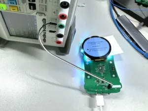
Since MEDICA, the badge has made several appearances at networking events. In parallel, our software team has been focusing on collecting and displaying heart rate data. Currently, we can collect raw sensor data showing a waveform from the EKG sensor. We then filter it and process it to reveal the dominant frequency – aka the heartbeat. The next step for this will be to create the UI elements to display this data.
Beyond the heart rate data, we would also like to display the data from one of our former projects, the Brainchild Smart Pacifier (see right) via Bluetooth. This device displayed pressure changes in a pacifier. The Smart Pacifier included a tablet app for displaying the data providing a bridge to then display that data on our badge. How cool!
We are also designing next generation electronics to address some of the electrical design limitations identified in the initial build and test phase.

The Future is Now, Next Stop: MTC Tech Conference!
Want to see the Smart Badge in action yourself? Come find us at MTC’s 5th Annual Technology Transformation Conference on February 29, 2024! We’d love to hear your feedback and big ideas for future features!
This project made it to MEDICA in only four weeks because of the power of Time Management, Close Cross Disciplinary Collaboration, and a focus on the Minimum Viable Product. This project was a snapshot of our typical approach to product development. It’s a balancing act between requirements, schedule, and budget. Every project is different, but these foundational pillars can contribute to success in any undertaking!
Check out our Product Development Guide to dive deeper into the details of how to optimize your own Development efforts! Or, reach out if you have a hard problem in need of solving!

Wondering How to Get Your Product
Development Process Right?